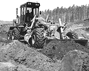
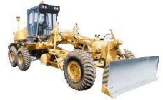
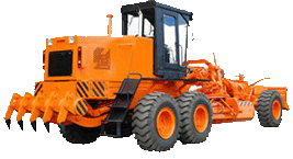
Working equipment of motor grader DZ-98B
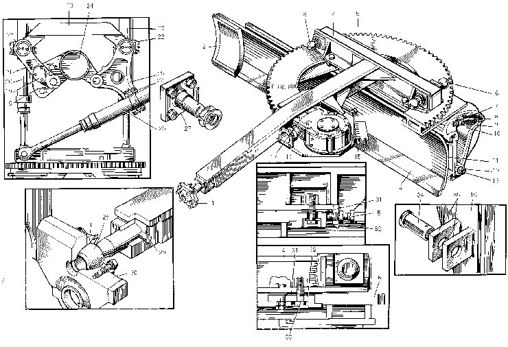
The traction frame with the mould board installed on it and traction frame suspension form a part of the working equipment of motor grader. Working equipment with full-turning mould board Traction frame. The front portion of the traction frame through the king pin 28 is connected to the main frame. The rear portion of the traction frame is suspended on three hydraulic cylinders ensuring the mound board setting in the required position.
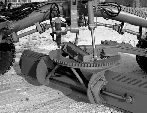
Box-section mould board 11 with changeable blades 2 and 14 is hinge-connected to brackets 10 in whose guides it can be displaced sideways with the help of a hydraulic cylinder. Bracket 10 is hinge-connected to other cylinders, which are rigidly connected to slewing circle 5. When bracket 10 are turned (along the slot lehgth), the mould board cutting angle changes. With the help of the slewing circle the mould board is turned either side in the plan, making a full revolution. The slewing circle with the brackets and mould board is connected to traction frame 4 with the help of straps 32.
The slewing circle together with the mould board turns in the guide backing plates by means of the mould board turn mechanism. Provision is made for adjusting the vertical clearance between the slewing circle and straps by means of gaskets 31, while the side clearance between the butt surfaces is adjusted with the help of adjusting bolts 15. The vertical clearance should be 0.5...3 mm, while the total side clearance, up to 6 mm. When the guiding slots of brackets 10 get worn in excess of 4 mm, fit the 067.37.11.072 clamps into the lower slots, available in the SPTA set.
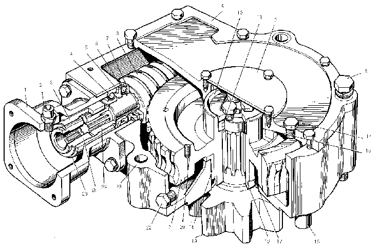
The mould board turn mechanism is mounted on the traction frame and consists of slewing circle 5, mound board turn reduction gear 17 and hydraulic motor. When the hydraulic distributor lever is engaged, working fluid under pressure flows into the hydraulic motor. Further rotation is imparted through worm 8, worm wheel 21, pinion-shaft 19 to the slewing circle. The sense of rotation is changed by shifting the distributor control lever in the opposite side.
1- spacer;
2- breather;
3- splined coupling;
4- bearing;
5- distance ring;
6- worm shaft;
7- thrust bearing;
8- worm;
9- reduction gear housing cover;
10- thrust washer;
11- sealing ring;
12- cover;
13- bolt fastening reduction gear to traction frame;
14- filling hole plug;
15- bronze bushing;
16- setting pin;
17- collar;
18- worm wheel hub;
19- pinion-shaft;
20- locking screw;
21- worm wheel;
22- drain hole plug;
23- reduction gear housing;
24- worm shaft splined bushing;
25- splined bushing of hydraulic motor shaft;
26- circlip
