Hydraulic system of motor grader DZ-98B
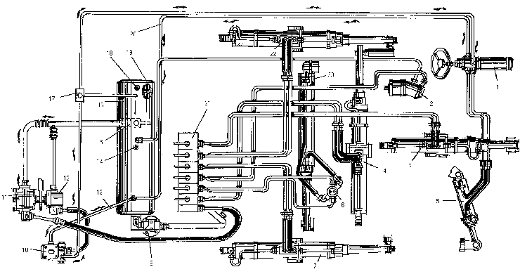
The hydraulic system serves for controlling the working members and steering mechanism, it also facilitates the clutch control. Since hydraulic system is provided with two delivery lines, carrying fluid from hydraulic tank 16 to the consumers, two circuits of the hydraulic system can be distinguished:1) the drive of the working members;
2) the drive of clutch booster 10 and steering mechanism.

Pressure in the hydraulic system circuits is being built up by two gear pumps, mounted on the reduction gear of the pump drive. The NSH-71E pump 11 serves for driving the working members, while the NSH-50 pump 12 is used to drive the booster and steering mechanism.
Working fluid comes to the pumps through the intake pipe of the hydraulic tank. On the intake pipe is mounted the valve 15, which, if required, shuts off the liquid flow from the hydraulic tank. The IO-71E pump delivers fluid into distributor 21, where from it flows to actuate the necessary unit. Distributor 21 receives a safety valve, adjusted to a pressure of 10-11 MPa (100-110 kgf/cm 2).
In the hydraulic system for driving the working equipment are used the hydraulic cylinders. Only for turning the mould board depending on a traction frame design are used either a hydraulic motor or to hydraulic cylinders.
In the hydraulic lines of mould board turning cylinders on the traction frame is arranged the valve block in which are two valves adjusted to a pressure of 18 +1 MPa (180+10 kgf/cm2). The hydraulic locks are mounted on the hydraulic cylinders (except for the mould board overhang cylinder) to preclude displacement of the working members with the distributor slide valves in neutral position. Fluid expelled from the unit spaces is drained through the distributor and filter 9 mounted on the hydraulic tank bracket. The filter is provided with a by-pass valve, which operates when the filtering element becomes clogged and lets the fluid flow directly into the hydraulic tank, by-passing the filter. The filter by-pass valve is adjusted to a pressure differential within 0.25-0.35 MPa (2.5-3.5 kgf/cm2), when operating on the working fluid warmed up to 50-60 0C. Hydraulic adapter 6 mounted in the hydraulic system serves for eliminating twisting of the hoses, when the blade turns. The NSH-50 pump Ref. 12 delivers fuel in clutch booster 10 and further via the pipeline in steering mechanism: hydraulic steering wheel 1 and hydraulic cylinder 5. To protect the units safety valve 17 is mounted in the pipeline, which operates at a pressure of 16▒0,5 MPa (160▒5 kgf/cm 2) and delivers a portion of fluid into the hydraulic tank. Fluid is drained out of the booster and steering mechanism also into the hydraulic tank via pipelines 13 and 20, respectively.
Checking and adjustment of pressure . To check the pressure make use of the T-piece available in the motor grader SPTA set (set of Spares, Tools and Accessories), connecting it between the unjoint ends of the line to be checked. A pressure gauge rated at 20-25 MPa (200-250 kgf/cm2) is installed into the T-piece.
Proceed to checking pressure at the temperature of working fluid in the hydraulic system being 40-50 0C.
After starting up engine, push the rod of the cylinder under check against the stop and check pressure ly the pressure gauge.
ATTENTION! UNSEALING AND ADJUSTMENT OF THE SAFETY VALVES OF THE HYDRAULIC DISTRIBUTOR AND THE STEERING AS WELL AS THE VALVE BLOCK IN THE HYDRAULIC LINES OF MOULD BOARD TURNING CYLINDERS ARE PERFORMED NECESSARILY ONLY AFTER TERMINATION OF THE MOTOR GRADER WARRAN-TY PERIOD. For checking pressure in the circuit of the hydraulic system of the working members make use of the adjusting screw of distributor 21 safety valve. Safety valve 17 is used to regulate pressure in the steering hydraulic system and in the NDM 200 - Y600 hydraulic steering wheel.
Adjusting screws of the valve block in the hydraulic lines of mould board turning cylinders are placed on the side surfaces of the block, closed by caps and jammed by lock nuts.


