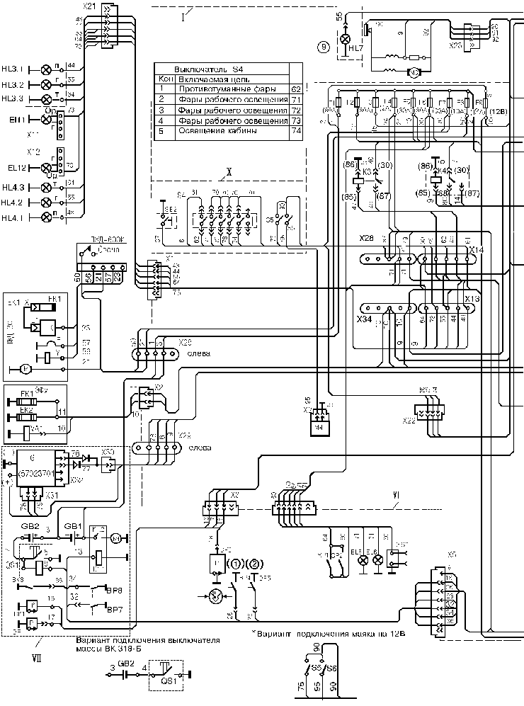
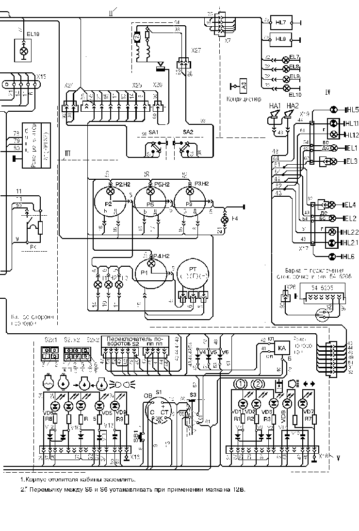
Electrical equipment of motor grader DZ-98B
Electrical equipment of the motor grader is connected via a single-wire circuit, the negative terminals of the electric energy sources and consumers are connected to the body ( "Frame" ) of the motor grader. Voltage in the board supply line is mixed: 12 and 24 V.The lists electrical equipment members and the electrical diagrams of motor graders are shown in appendix 2.


The power sources are two storage batteries (6 CT-190A) and generator operating together with the regulator.
The main power consumers are the starter; electric motors of cab heater, engine starting preheater and windscreen wiper; glow plugs of electric starting preheater and preheater; lighting, signalling and control systems.
Connected to the 12 V mains are the electric motors of the cab heater and windscreen wipers.
Attention! After job termination all the consumers of the electric circuit at 12 V should be switched off to prevent the storage batteris discharging.
Lighting and signalling devices. To illuminate the site of motor grader operation six headlamps are arranged on the cab and two headlamps on the rear part of the engine facing. These headlamps are provided with the bulbs with two filaments, the lower beam filament being connected only. The road is lighted during a transport mode of operation of the motor grader by two headlamps working in the lower and upper beam modes. The head front lamps are arranged over the fore wheels on the ends of the tubular bracket. Two fog lamps are installed on this bracket from below. The head front lamps are hinge-connected to the bracket and are able to change their position. The rear head lamps have the adjusting screws allowing to adjust their position in horizontal and vertical plane. Installed from rear on the facing are two three-section lights intended for indicating the turns and outlines of the motor grader, also for producing a light signal during braking (stop light). The front head lamp bracket receives two lights intended for indicating the turns and outlines of the motor grader at the front. A dome lamp fitted in the cab roof serves for lighting the driver's working site.
A socket for connecting the portable lamp is available under the cab at the left-hand side. Mode of operation of the motor grader units is checked by the electric devices and light diodes used as the pilot lamps. The light diodes are united in a signal panel on the steering column. The instruments are arranged on the dashboard. They include the engine oil and pneumatic system air pressure indicators, engine coolant temperature indicator, pressure gauge and hourmeter.
Glow-plug preheater. The engine YAMZ-8482.10-01of the motor grader is equipped with a glow-plug preheater which facilitates the starting up of the engine. It comprises two pin-type glow plugs, thermal relay and electromagnetic fuel valve. The glow-plug preheater is switched on with the help of a starter switch which is turned into the second position hereat. Readiness of glow-plugs for operation and moment of the engine starting by the starter are checked by the lamp on the dashboard. Lighting of the lamp is indicative of sufficient heating of the plugs and delivering of fuel to them by the electromagnetic valve. After this the starter may be switched on.
Light beam adjustment is performed on a level ground using a screen positioned at a distance of 10 m from the motor grader. Stop the motor grader in front of the screen and turn on the head lamps. Make sure that the lamps function correctly manipulating the switch for the upper and lower beam. Turning on the upper beam, close one of the head lamps with ligh-tight material. Position another head lamp so, that the light spot centre of the head lamp coincides with the mark on the screen and secure it. Proceed in the same manner to aim the second head lamp. The light spots of both the head lamps should lie on the same height and produce a common scattered light spot.


