Two-section brake valve
Two-section brake valve is designed for controlling the actuating mechanisms of the motor grader service brakes.The brake valve has two independent sections, arranged in series and fed from the recievers of the individual circuits.
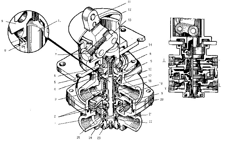
The brake valve consists of body upper half 17 and body lower half 1 interconnected by means of four bolts, supporting plate 5 with lever 11 upper valve 8 and lower valve 24, upper piston 15, large piston 19 and small piston 20, equalizing element 9 of the valve and piston springs, also the sealing rings.

Outlets I and II of the body upper and lower valves are connected to the receiver, while outlets III and IV, to the brake cylinders through the intermediate air apparatuses with the brake cylinders. In the initial position (the brake pedal released) the brake valve connects the air cavities of the brake cylinders through the holes in outlet port 23 through outlets III and IV to the atmosphere. At this, upper piston 15 under the action of spring 16 occupies the topmost position, the valve outlet port is opened, outlet III communicates with the atmosphere.
Upper piston 8 under the action of spring 3 is pressed to the seat of the body upper half, outlet I is disconnected from outlet III. Large piston 19 and small piston 20 under the action of spring 21 occupy the topmost position, the outlet port of lower valve 24 is opened, outlet IV communicates with the atmosphere. Lower valve 24 is pressed with spring 25 to the seat of the body lower half, outlet II is disconnected from outlet IV.
When the brake pedal is depressed, lever 11 turns around its axle 7, presses pusher 14 with roller 13, the pusher compresses equalizing element 9 through spring plate 6, thus moving upper piston 15 down. In moving down, the piston compresses spring 16, shuts off the outlet port, disconnecting outlet III from the atmosphere, and throws valve 8 off the seat. Compressed air fed to outlet I through the open valve comes to outlet III and further to the wheel brakes of the motor grader rear axle till the effort applied to the lever is equalized by the air pressure exerted onto piston 15 (follow-up action).
At the same time the compressed air through the hole in outlet III flows into the space above large piston 19. The piston having a larger area moves down under insignificant pressure in the above-piston space, moves small piston 20, compressing spring 21. The small piston shuts off the outlet port, disconnecting outlet IV from the atmosphere and throws valve 24 off its seat. Compressed air fed through the open valve to outlet IV and further to the wheel brakes of the motor grader intermediate axle. Compressed air under pistons 19 and 20 equalizers the force, acting on piston 19 from above in such a way that pressure in cavity IV becomes equal to the force exerted on the lever (follow-up action). The size of the pistons and spring 21 are selected so that pressures in outlets III and IV are practically equal depending on the force exerted on the lever. When the lever is in the intermediate positions, the lower section is controlled pneumatically.
With the lever in the extreme position or in case of damage of the upper section circuit, the upper piston, in moving down, actuates stem 10 of small piston 20 with screw 4 thus displacing the small piston down. The said piston, in its turn, shuts off the outlet port and opens valve 24.
When the force is relieved from the lever, the upper piston under the action of spring 16 moves up, valve 8 under the action of the spring is pressed to the seat, while the piston goes on moving, opening the outlet port and connecting outlet III with the atmosphere. Pressure in the space above large piston 19 drops, pistons 19 and 20 move up due to pressure differential and the action of spring 21, valve 24 is pressed to its seat, the outlet port opens and outlet IV communicates with the atmosphere.
In case of a mechanical action on small piston 20 the lower section becomes released similarly, when pressure is relieved from stem 10.


