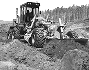
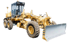
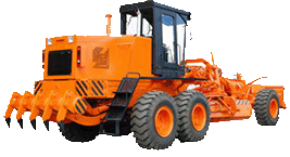
The DZ-98B motor grader
The motor grader is a self-propelled earth-moving and grading wheeled machine,whose principal working member is mould board 12 and the auxiliary one is scarifier,as well as bulldozing 16 or scarifying equipment tracklaying equipment or snow removal equipment (according to complete set). 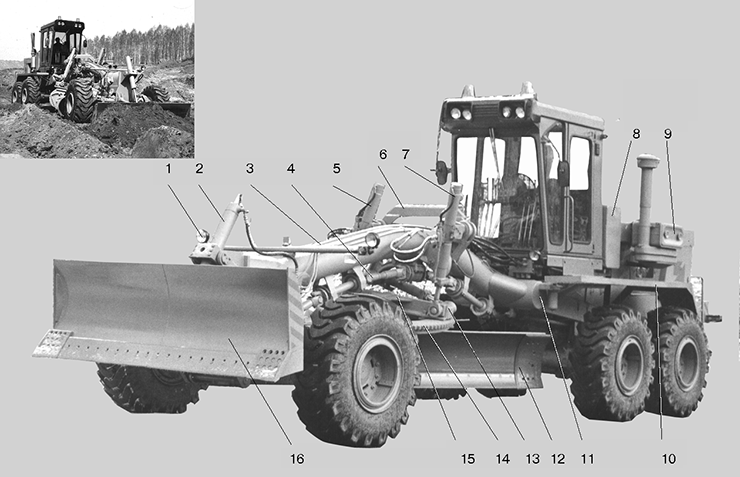 All the models of motor graders are maximum unified and differ by the engine and auxiliary working eguipment.
The DZ-98B.1, DZ-98B.3, DZ-98B.5, DZ-98B.7, DZ-98B.9 motor graders and the complete sets are provided consistently with next diesel engines: YAMZ-8482.10-01, Y1D6-TK-C5, YAMZ-240G, YAMZ-238HD3, YAMZ-238HD2.
The motor grader transmission is of mechanical type.
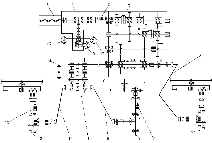
The gearbox including the step-up gear ensures 6 forward and 6 reverse speeds. Clutch, gearbox, reduction gear drive of hydraulic pumps and distributing reduction gear are combined in an integral block. These units have the communicating oil tanks and the common lubrication system.
The motor grader is equipped with three drive axles.
 All the models of motor graders are maximum unified and differ by the engine and auxiliary working eguipment.
The DZ-98B.1, DZ-98B.3, DZ-98B.5, DZ-98B.7, DZ-98B.9 motor graders and the complete sets are provided consistently with next diesel engines: YAMZ-8482.10-01, Y1D6-TK-C5, YAMZ-240G, YAMZ-238HD3, YAMZ-238HD2.
All the models of motor graders are maximum unified and differ by the engine and auxiliary working eguipment.
The DZ-98B.1, DZ-98B.3, DZ-98B.5, DZ-98B.7, DZ-98B.9 motor graders and the complete sets are provided consistently with next diesel engines: YAMZ-8482.10-01, Y1D6-TK-C5, YAMZ-240G, YAMZ-238HD3, YAMZ-238HD2.The motor grader transmission is of mechanical type.
The gearbox including the step-up gear ensures 6 forward and 6 reverse speeds. Clutch, gearbox, reduction gear drive of hydraulic pumps and distributing reduction gear are combined in an integral block. These units have the communicating oil tanks and the common lubrication system.
The motor grader is equipped with three drive axles.
Power is transmitted to the front axle through the cardan transmission. It may be cut off, if reguired.
The intermediate and rear axles are connected to the main frame through a suspension made up of swinging equalizers and torque rods.
The front axle is articulated to motor grader frame 3,thus ensuring transverse cushioning of the axle. The front wheels are turned by means of a hydraulic mechanism of follow-up action. The hydraulic system of the steering mechanism and the working member control hydraulic system have common tank 11 for working liquid. The mouldboard is secured to traction frame 13 which,in its turn,is attached to the front and middle portions of motor grader frame 3 by means of a ball joint and suspension 6 with hydraulic cylinders 5 and 7, respectively. Design of traction frame suspension 6 ensures vertical mounting of the mouldboard at both sides of the motor grader.
The traction frame is equipped with the guides which allow the mouldboard to move at both sides of the motor grader with the help of the hydraulic cylinder.
The complete turn of the mould board in the horizontal plane according to traction frame construction is effected by hydraulic motor with the reduction gear 15 or by hydraulic cylinders of mould board turn.
The front portion of the motor grader frame is thick-wall pipe which space being used as main receiver of the pneumatic system.The space of the I.h. side member of the frame rear portion is used as an auxiliary receiver.
Illustrates the kinematic diagram of the motor grader.
