The clutch servomechanism (booster)
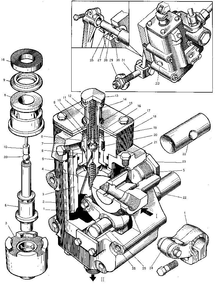
serves to reduce effort on the pedal when the clutch is controlled, i.e. its use improves the driver's operating conditions.The booster consists of housing 2 attached to the fitting plane of the clutch housing to the right in the direction of the motor grader travel. Piston 3 moves inside the housing, spring 4 is inserted into the piston cylindrical hole.With its second end the spring thrusts against valve 6,istalled to move in the bushing of cover 7. The valve has a cylindrical guide in its upper portion, onto which rod 12 is ins-talled. The spring with its one side trusts against the shoulders of valve 6,while with the other side,against rod 12.The rod is held in the initial position with circlip 14 installed in the recess of valve 6. Spring 11 is inserted into the valve hole.With its upper end the spring thrusts against plug 13, screwed into the rod,while with the lower end, against stem 10.Ball 20 serves as a by-pass valve. Cover 7, into which the bushing is mounted,is bolted to the upper part of the housing. Rod 12 is sealed with cup 16 and dust boot 15. Adjusting gaskets 19 are fitted under the butt end of spring 11. They are used to set dimensions 3.6 + 0.1 mm. Take measurements when plug 13 is not screwed in.

The booster housing has a through cylindrical hole, into which slide valve 22 is inserted. This slide valve serves to divide the flow of oil delivered by the pump into two flows, feeding the hydraulic system of two independently operating mechanisms (booster and steering mechanism). One of the flows enters the above-piston space of the booster, while the other, through a special pipe union, comes to the steering meßhanism distributor of the motor grader.
The hole in the slide valve body is closed with plugs 23. Piston 3 rests on roller 24, fitted on the axle of lever 1. The latter is rigidly fixed on shaft 25. Rigidly fitted on shaft 25 end on the key is the lever, which is hinged-connected through a special pin to tie 31.Spherical nut 29 and locknut are screwed onto the tie threaded portion. With its sphere the nut enters the spherical seat of the clutch yoke.
The booster design provides for disengagement of the clutch applying a small effort. In case of the hydraulic system failure or with the engine not running the effort on the pedal reaches 700 N (70 kgf). During the motor grader operation,when the clutch is engaged,rod 12 of the booster is in the initial position (top most position). Working fluid from the NSHś-50 pump flows through the slide valve into the above-piston space of the booster, then along through holes of piston 3 into the lower space, where from it is drained into the tank via the pipeline. At this, differnce in pressure in these spaces is insignificant, therefore piston 3 is in the initial position.
When the clutch pedal is depressed,the effort is transmitted via the system of levers and ties to rod 12 and valve 6,which move down simultaneously, tapered part of valve 6 tending to separate the above-piston space and lower space,which results in rising of working fluid pressure in the above-piston space. Under the action of pressure difference in the spaces, piston 3 starts moving down and in actuating roller 24,makes lever 1 turn through a definite angle. Lever 1 is rigidly connected to the lever which actuates by means of tie 31 and spherical nut 29 clutch release sleeve yoke 28, making the latter displace together with the release sleeve, which disengages the stack of clutch through release levers 5.At the instant the discs are released, pressure in the above-piston space of the booster reaches 1.6 MPa (16 kgf/cm 2).
With further depression on the clutch pedal,when the clutch driven shaft is to be braked, rod 12 is displaced relative to valve 6. The springs are compressed and actuate valve 6, which leads to a sharp rise of pressure in the above-piston space up to 3.8MPa (3kgf/cm 2), and hence to an increase of effort on the release yoke and to braking of the clutch driven shaft by means of the stop.
If pressure in the above-piston space rises above 3.8 MPa (38 kgf/cm2), ball 20 is depressed and the working fluid owerflows to drain through the holes of the bushing in cover 7.
When the foot is removed from the pedal, rod 12 and valve 6 under the action of springs 11 and 4 return into the initial positions,making free the through holes in position 3, resulting in that pressure in the above-piston space and in lower space and in lower space becomes equal. The leverage returns into the initial position under the action of the force of the clutch springs.
Adjustment of clutch together with booster
1.Booster with plug 32.
Adjustment sequence:
1) remove the shutters under the cab and hatches on the clutch housing;
2) uncotter and unscrew horned nuts 31;
3) unscrew spherical nut 29 on tie 31 and place a 21+1 mm thick spacer (available in the tool kit suppled with each motor grader) between the release sleeve disc and stop disc;
4) unscrew the plug 32 on the booster housing, place a 2+1 mm spacer (available in the tool kit suppled with eash motor grader) between piston 3 and roller 24;
5) displacing the spacer between piston 3 and roller 24, at the same time screw inspherical nut 29 till piston 3 thrusts against valve 6 (at this instant the effort required to move the spacer rises sharply); 6) lock spherical nut 29 by means of a locknut;
7) rotating nuts 31 set a uniform clearance within 0...0.2 mm between sleeve 2 and levers 5, then cotter the nuts on bolts 6;
8) remove the 2+1 mm thick spacer,screw in the plug in the booster housing. After spacer is removed, a clearance of 2...3 mm will be evident between piston 3 and valve 6,which ensures free draining of the fluid out of the above-piston space;
9) remove the 21+1 mm thick spacer.
2. For booster without plug 32 and with rod 12 the head diameter of which is not in excess of the rod diameter.
Adjustment sequence:
1),2),3) perform the operations analogous with the operations of the corresponding items in the above-mentioned adjustment;
4) adjust the free travel of the booster rod by means of spherical nut 29 (the rod is recessed when the pedal is depressed). Height measurement difference of the rod in free state and the rod depressed against the stop should be 14 +1 mm.
5) perform the operations analogous with the operations of the item 6),7),9) in the above-mentioned adjustment;
6) check the oil pressure at booster drain. The oil pressure should be not more than 0.1 MPa (1 kgf/cm2).
As the clutch friction discs become forn,readjust the clutch with booster in due time in the above-mentioned manner.


