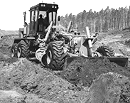
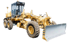
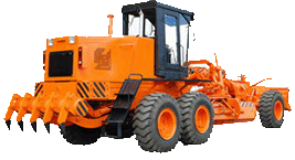
The PJD-30 starting preheater motor grader DZ-98B
(abbreviated name-preheater) serves to prepare the engine for starting at subzero ambient air temperature by warming-up the cooling liquid and the oil.PJD-30 preheater specification
| Type | liquid |
| Heating efficiency, ccal/h | 26 000 |
| Storage battery voltage, V | 24 |
| Power consumption, W | 340 |
| Fuel | diesel fuel |
| Fuel consumption, kg/h | 4,2 |
| Exhaust gas temperature, ░C | 500 |
| Current intensity consumed by ignition plug, A | 7 |
| Fuel ignition | by heating plug |
| Source of high voltage | TK 107 |
| Pump unit electromotor | ME 252 |
| Electromagnetic valve | PJD-30-1015500 |
| Liquid pump capacity, l/min | 30 |
| Capacity of the blower, kg/h | 90 |
| Maximum head of the fuel feed pump, MPa (kgf/cm 2) | 1,2 (12) |
The heater consists of the following main units:
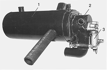 1) the boiler 1;
2) the burner 2;
3) the electromagnetic valve 3 with the fuel electroheater and the injector;
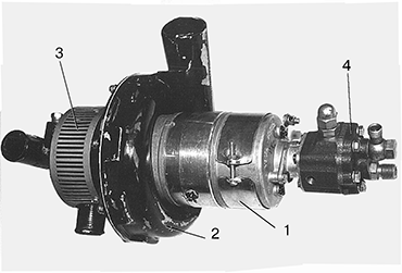 4) the pump unit incorporating the electric motor, the blower, the water pump and the fuel feed pump;
5) the source of high voltage and the heating plug for fuel ignition;
6) the control instrument board of the preheater.
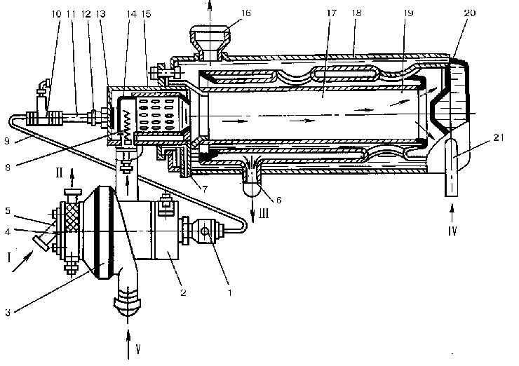 The boiler is a solid welded construction comprising four cylinders, which are placed one into the other. The first (external) and the second cylinders form the external water jacket 18. The space between the second and the third cylinders forms the reverse flow gas duct 20. The internal water jacket 19 is between the third and the fourth cylinders. The space inside the fourth cylinder is used as the combustion chamber 17. To ensure proper circulation of the cooling liquid, the external and the internal water jackets are interconnected with the aid of three 50 mm dia. holes formed by three branch pipes passing through the reverse gas duct.
The burner consists of the outer cylinder 15 (with the fastening flange welded thereto and the cover) and the inner cylinder 14. Fitted between the external cylinder cover and the inner cylinder is the primary air swirler 13, while three rows of ports in the inner cylinder are designed for supply of the secondary air to the combustion chamber. The primary air is used, mainly, to improve the spray of the fuel delivered by the injector, whereas the secondary air ensures its total combustion.
The electromagnetic valve is made as a unit with the injector and the fuel electroheater. The valve serves to switch on and off the fuel feed to the burner. The fuel electroheater heats a fuel portion before the preheater start. The injector supports fuel spraying needed for combustion.
The pumping unit consists of the air blower impeller 3, the water pump impeller 10 (two are in a common casing) and geared fuel pump 5 driven by electric motor. The air blower and the water pump are fastened to the motor frame at the longer output end of the shaft 6, while the fuel pump-on the opposite side. The fuel pump frame has a threaded drain hole for fuel drain seeped through the stuffing boxes.
The source of high voltage and the ignition plug interconnected by a high voltage conductor, form the electric ignition system.
The control of the starting preheater is of a remotely controlled type and executed from its control panel installed near to the preheater for the YAMZ-8482.10-01 engine and inside the cab on the rear wall for other engines.
Operation of the starting preheater
From the lower manifold of the radiator the cooling liquid is primed by the water pump of the priming unit through the branch pipe I into the branch pipe II and flows in the boiler through the branch pipe IV.
In the boiler the cooling liquid, passing through the external jacket into the internal jacket, forms two flows, which flow about the combustion chamber and the reverse gas passage.
In burner air is primed by blower through the branch pipe V.
The fuel is primed by the fuel feed pump of the pumping unit from the tank to the electromagnetic valve. When the valve is closed, a portion of fuel is delivered by the electroheater before preheater start-up. When the valve is opened, the fuel flows under pressure through the nozzle in the burner, where it is mixed with injected air. The electric ignition system ignites the fuel-air mixture during starting-up. The plug is cut out and burning continues automatically. The heat generated by the fuel burning heats the cooling liquid, passing through the boiler and divided into two flows. The heated liquid flows in the jacket of the engine cylinder unit through the boiler branch pipe 16. The exhausted gases are removed from the boiler through the branch pipe III.
How to start up and switch off the pre-heater
For the preheater starting-up it is necessary:
a) check antifreezing agent in the system by short-time opening the drain cocks of the cooling system;
b) check the fuel availability in the tank, open the cock feeding the fuel to the preheater and circulate the fuel system by the hand fuel feed pump;
c) switch on the "Frame" switch;
d) on the preheater control board cut in the switch 1 of the pumping unit electric motor to the position RABOTA (operation) for 10-15 s. At the same time the switch 2 of electromagnetic valve should be in the lower position, i.e. it should be cut off;
e) depress the push button 3 and keep it some time according to the ambient temperatures
20 s to - 20 0C
30 s to - 30 0C
60 s to - 40 0C
90 s to - 50 0C
f) on expiration of above mentioned time shift the switches 2 and 1 of the electromagnetic valve from the lower position to the upper one, i.e. they should be cut in;
g) cut in the heating plug by turning the switch 4 to the left in the spring-loaded position and keep it in this position to the appearance of the characteristic roaring in the boiler, meaning that the fuel is ignited in the burner;
h) release the plug switch; the switch resets automatically; the heating plug is switched off. The ongoing smooth roaring in the boiler means a stable operation of the preheater.
It the preheater doesn't operate during 20-30 s after switching-on the heating plug, it is necessary:
- release the plug switch;
- switch off the preheater (see below);
- restart-up in 1 min. according to the item d)...h).
At two unsuccessful kingling attemps a malfunction should be found and corrected. Duration of the preheater operation needed for warming-up the engine depends on the ambient temperature.
In order to stop the operation of the preheater, it is necessary:
- shift the switch 2 of the electromagnetic valve in the lover position. Scavenging of the combustion chamber and the gas duct is made to remove the removing combustion products and obviating the possibility of the gas popping at the subsequent starting;
- on expiration of time about 15-20 s switch off the electric motor of the pumping unit by the switch 1;
- cut off the cock feeding the fuel to the preheater.
Adjustment of the starting preheater
A stable operation of the starting preheater is defined by uniform roar of the flame and by a light-colour of the exhaust gases at the preheater outlet. The exhaust should be a smokeless and a flameless. Otherwise it is necessary to adjust the starting preheater by means of the screw 16 of the reducing valve of the geared fuel pump .
It is necessary:
- unscrew the captive nut 15 on the fuel feed pump of the pump unit;
- loosen the lock nut 14 of the adjusting screw;
- adjust the normal preheater operation by turning the adjusting screw clockwise (the fuel feed is increased) or counterclockwise (the fuel feed is decreased).
It is recommended to adjust the fuel feed at the temperatures not over than - 5 0C.
Sequence of the starting preheater use
It is recommended to use the preheater of the Y1D6-TK-C5 engine at ambient temperatures below 8 0C, of other engines - at subzero temperatures. At subzero temperatures in order to effective engine warming it is recommanded the following operation sequence:
- switch on the preheater in operation and raise the cooling liquid temperatures to 70 0C;
- switch off the preheater and let heat disribute
along the crankcase and sump of the diesel engine;
- when the temperature of the cooling liquid drops down to 50...600 C, switch the preheater again and raise temperature up to 80...85 0 C;
- switch off the preheater and close the cock of the fuel feeding to preheater.
Safety precautions
1. Operation of the preheater and start-up of the diesel engine are possible only when adequate amount of the cooling liquid is available in the system. Non-observance of this requirement may lead to burning- through of the boiler, crancking in the cylinder sleeves and unit head, etc.
2. Preclude soiling the parts placed close to the exhaust fitting pi pe of the preheater boiler to avert fire.
3. Simultaneous operation of the preheater and the diesel engine is prohibitive, since in operation the cooling liquid streams have the opposite direction. Therefore, in order to prevent the failure of units of the engine cooling and preheating system, it is necessary to stop the preheater operation only following which to start-up the engine.
4. Do not leave the motor grader when the preheater operates. When the flame or smoke appear in the exhaust gases, the preheater should be immediatly switched off.
