Pneumatic system of motor grader DZ-98B
The pneumatic system of the motor grader ensures the drive of the wheel brakes and control of the latch of the traction frame suspension mechanism lever. Compressor 3 serves as a source of compressed air on the motor grader.
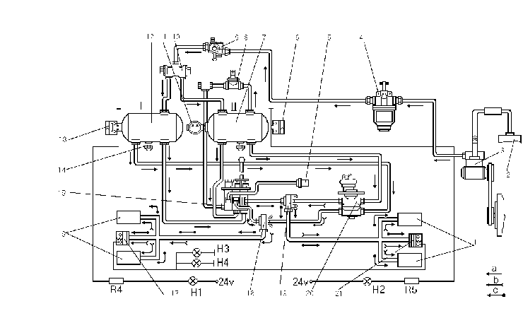
Diagram of pneumatic system
1,16- brake air cylinders of rear axle, intermediate axle;
2- engine intake manifold;
3- compressor;
4- antifreezer;
5- air latch;
6,13- circuit pressure alarm pickups;
7- receiver;
8- single valve;
9- pressure regulator;
10- double safety valve;
11- pressure gauge;
12- minor receiver;
14- condencate drain cock;
15- air distributor;
17- mid axle brake application pickup;
18- circuit I two-line valve;
19- curcuit II two-line valve;
20- brake valve;
21- rear axle brake application pickup;
R4,R5- resistors;
H1,H2- signal panel lamps;
H3,H4- stop lights;
a- air flow;
b- brakes applied;
c- emergency brakes applied
Compressed air is fed from compressor into antifreezer 4, whose switching on at the temperature below +5 0C ensures saturation of compressed air of pneumatic system by alcohol vapours and prevents condensate freezing. Then compressed air enters pressure regulator 9, which maintains automatically the required pressure of the compressed air in the pneumatic drive. From the pressure regulator air flows through double safety valve 10 to the individual brake drive circuits. From the receiver 7 through the single safety valve 8 is performed a bleed-off of compressed air for piston-latch 5 of traction frame lever. At a compressed air pressure below 0.55 MPa (5.5 kgf/cm2) the valve shuts off the latch line.


