Air distributor
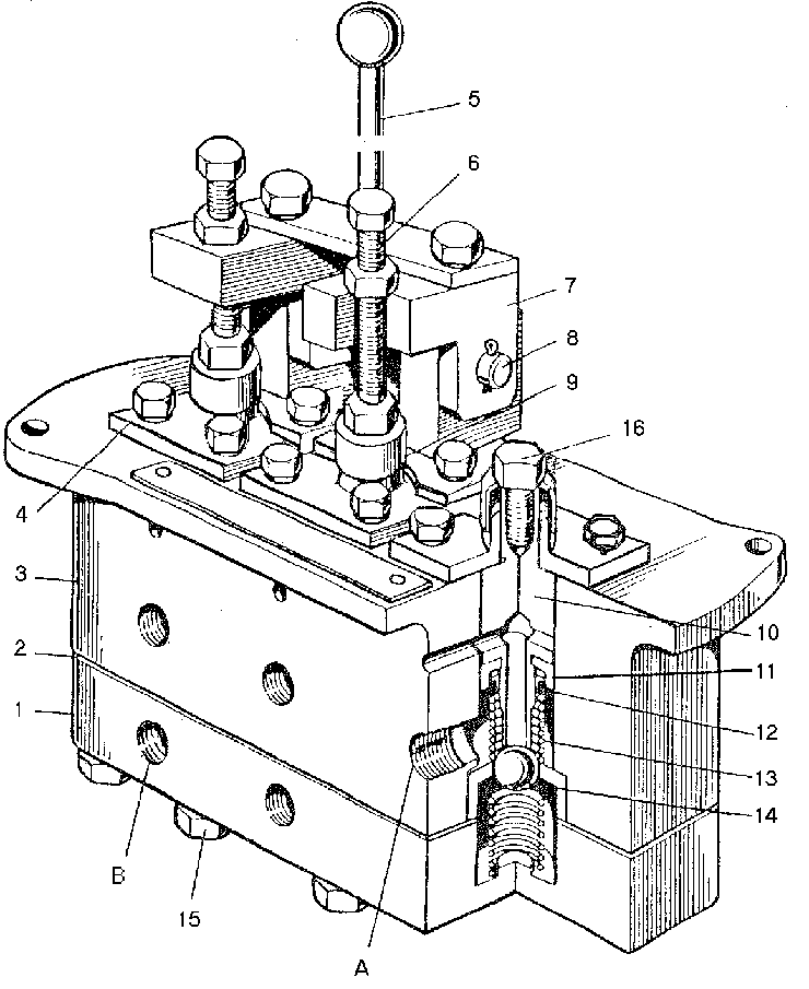
The air distributor is designed to feed the compressed air to the brakes in case of emergency braking of the motor grader, also to feed air to the latch of the traction frame suspension lever. The air distributor has three independent sections. Two of them are used for emergency braking and are controlled by one handle. The sections are fed from different receivers. The third section is intended for supplying the compressed air to the latch of the traction frame suspension mechanism lever. It is fed from the receiver through the single safety valve and is controlled by a foot pedal. The air distributor comprises body 3 and tray 1. Each section comprises stop 9, cover 4, slide valve 10, springs 13 and ball 14. Cavities B are connected to the receiver, while cavities A, to the lines running to the brakes and traction frame suspension lever latch. In the initial position cavities A communicate with the atmosphere through hollow slide valve 10 and holes in body 3. When special button 16 is depressed or handle 5 is pulled, slide valve 10 moves down, overcoming the force of spring 13 and with its seat fits ball 14, thus disconnecting cavity A from the atmosphere.
When the slide valve moves farther, ball 14 departs from the sleeve seat, cavity A becomes connected with cavity B and the compressed air starts flowing from the receiver to the brakes or traction frame suspension lever latch.
When handle 5 or special button 16 is released, slide valve 10 under the action of spring 13 moves up, ball 14 fits the sleeve seat, thus disconnecting cavities B and A. With further displacement the seat of slide valve 10 departs from ball 14 and cavities A communicate with the atmosphere.
The two-line valve is designed for controlling one of the lines. The valve joints the working drive and the emergency drive of brakes and may be controlled either by the brake valve or by the emergency braking air distributor. Mounted inside the valve is the diaphragm which separates the circuits of the brake valve and air distributor. When the compressed air is fed to one of the two valve inlets, the diaphragm overlaps the opposite inlet, thus preventing bleeding of air when one of the circuits is faulty.


