Hydraulic tank of motor grader DZ-98B
The hydraulic tank body is a part of the motor grader frame structure. Working fluid is primed into the tank through filler neck 7 closed with plug 6.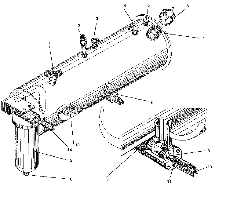
A gauze strainer is available in the filler neck. Installed in the low part of the hydraulic tank is valve 8, which is capable of shutting off flow of fluid into intake pipeline 12 in case of necessity. Clamp 10 attached to stem 9 serves to control the valve. To shut off the flow of fluid push the stem into the valve body as far as it will go. With the valve in the open (operating) position the stem should be drawn out of the body, the clamp lowered thereon and cottered. Fluid is drained out of the hydraulic steering wheel and booster through pipe union 1, while out of the hydraulic motor and safety valve of the steering control, through pipe unions 3 and 4, res-pectively. The level of fluid in the hydraulic tank is checked with the help of oil dipstick 5. The hydraulic tank cavities communicate with the atmosphere through breather 2. When draining the working fluid, screw plug 13 out of the hydraulic tank. Filter 15 of the hydraulic system mounted on the hydraulic tank bracket is intended for purification of fluid expelled from the hydraulic cylinders of the working members. In the filter body is mounted a paper filtering element which cannot be ever cleaned. The by-pass valve,mounted in the filter, operates due to pressure differential, thus safeguarding the filtering element against breakage. Sediment accumulated in the filter is drained through the hole, closed with plug 16. The pumps of the hydraulic system are similar in design, but differ, mainly, by dimensions of the parts affecting the delivery.
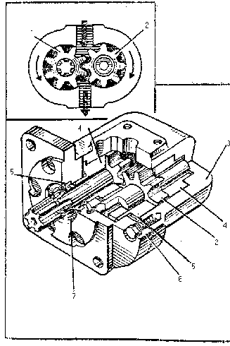 The hydraulic pump comprises body 3, cover 6 and the pumping unit, incorporating driving gear 1, driven gear 2, four bushings 4, four springs and a plate.
All the seals in the pump are made as round rubber sealing rings.
The pump body is made of aluminium alloy. Its side surfaces bear the plates where four threaded holes are drilled for fastening the fittings of the intake and delivery pipelines.
The bores for the gears and bushings are made in the body. The bushings are made of bronze. They serve as the gear supports and seal the butt surfaces of the gears. The guide springs ensure mutual disposition of the bushings during reassembly. In order to decrease the inner oil leakages in the pump through the clearances between the butt surfaces of the gears and bushings an automatic adjustment of clearances at the gear butts is used. This adjustment occurs automatically.
Oil from the delivery chamber via the slot comes into the cavity above the bushings and tends to press movable bushings 4 to the gear butts, thus eliminating the clearance between the butts of the bushings and gears. At the same time, the bushings at the end of the gears also are pressed by the oil pressure, but on the smaller area.
Thus, a resulting effort pressing the bushings to the gear butts is not great and is not a case of rapid wear.
The oil pressure at the end of the gear teeth is distributed non-uniformly.
To avoid skewness of the bushings due to non-uniform pressure application a part of their butt surface is isolated against the action of high pressure by a rubber seal.
The rubber sealing rings prevent leakage of oil out of the cavity under high pressure.
Oil, seeped through the gear journals, enters through the holes in the driven gear cover to the cavities connected to the suction chamber.
Thus, the whole amount of leaked oil accumulates in the pump suction line.
The drive end of the driving gear shaft is sealed with rubber movable collar 5.
The hydraulic motor serves to convert the energy of the working fluid into the rotary motion of the actuating mechanism. Due to this fact, the moul board is able to turn with the use of the hydraulic system.
The hydraulic pump comprises body 3, cover 6 and the pumping unit, incorporating driving gear 1, driven gear 2, four bushings 4, four springs and a plate.
All the seals in the pump are made as round rubber sealing rings.
The pump body is made of aluminium alloy. Its side surfaces bear the plates where four threaded holes are drilled for fastening the fittings of the intake and delivery pipelines.
The bores for the gears and bushings are made in the body. The bushings are made of bronze. They serve as the gear supports and seal the butt surfaces of the gears. The guide springs ensure mutual disposition of the bushings during reassembly. In order to decrease the inner oil leakages in the pump through the clearances between the butt surfaces of the gears and bushings an automatic adjustment of clearances at the gear butts is used. This adjustment occurs automatically.
Oil from the delivery chamber via the slot comes into the cavity above the bushings and tends to press movable bushings 4 to the gear butts, thus eliminating the clearance between the butts of the bushings and gears. At the same time, the bushings at the end of the gears also are pressed by the oil pressure, but on the smaller area.
Thus, a resulting effort pressing the bushings to the gear butts is not great and is not a case of rapid wear.
The oil pressure at the end of the gear teeth is distributed non-uniformly.
To avoid skewness of the bushings due to non-uniform pressure application a part of their butt surface is isolated against the action of high pressure by a rubber seal.
The rubber sealing rings prevent leakage of oil out of the cavity under high pressure.
Oil, seeped through the gear journals, enters through the holes in the driven gear cover to the cavities connected to the suction chamber.
Thus, the whole amount of leaked oil accumulates in the pump suction line.
The drive end of the driving gear shaft is sealed with rubber movable collar 5.
The hydraulic motor serves to convert the energy of the working fluid into the rotary motion of the actuating mechanism. Due to this fact, the moul board is able to turn with the use of the hydraulic system.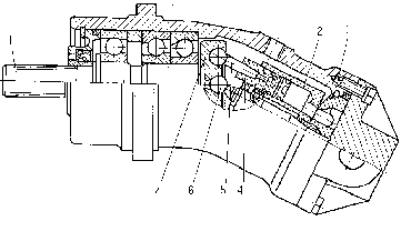
The hydraulic motor is of a piston-action type. Interaction between output, shaft 1 flange 7 and pistons 4 is effected through connecting rods 5 and powerless two-joint cardan shaft 6, which ensures synchronous rotation of output shaft 1 and cylinder block 2. Owing to the axial deflection of the cylinder block relative to the output shaft flange and ball-joint of the connecting rods, the pistons besides reciprocating motion along the block axis attain rotating together with the block. Each piston performs forward and reverse stroke per one revolution. As one piston moves from fixed distributing disc 3 by the action of the working fluid, the other piston moves to the distributing disc and guides the working fluid of its cylinder to drain. For the fluid intake and outlet from the fixed ducts into the cylinders of the rotating block a butt distribution is used with the fixed distributing disc.