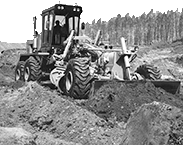
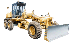
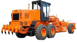
Controls of motor grader DZ-98B and driver's working place
The controls of all the units and instruments of the motor grader are arranged in the cab exclusive of the YAMZ-8482.10-01 engine starting preheater dashboard which is located near by the starting preheater. The motor grader set controls are located on the board under the cab roof.Controls and driver's working place of all the models of motor graders are manufactured equally,except a fuel feed control mechanism and dashboard .
A fuel feed control mechanism of the Y1D6-TK-C5 engine is different by availability of a control lever which allowes to change manually a fuel feed and to stop the diesel engine.
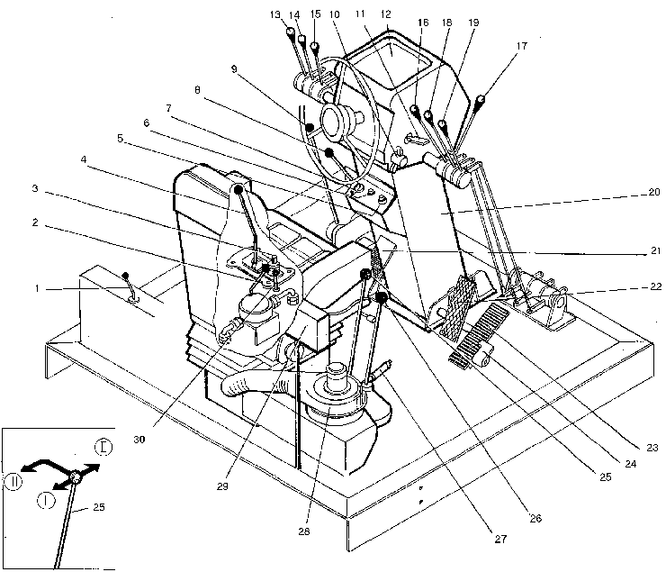
To add to the driver's comfort, his seat is made cushioned and is adjustable to suit the driver's height and mass. With that end in view the cab is equipped with adjustable steering column 21 and heater 29 working on the wormed liquid of the diesel engine cooling system.
Heater control. Heater 29 fan is actuated by a toggle switch available on switch board 30.The heater is able to operate in two modes which are set by handle 1. While the handle is being pulled,air circulates only in the cab,while being pushed,fresh air is added to that circulating in the cab. In summer air is not supplied in the cab and the heater fan is used to ventilate the cab interior.
Steering column 21 is equipped with a mec-hanism which allows to tilt either the column proper or to turn its control panel 16 into the position convenient for the driver.Two levers serve 20 for this purpose. For tilting the column,pull the levers.The control panel 16 should be turned after clamp 13, fastening the said part,is loosened.
Swith 14 mounted on the steering column is intended to bring into action the horn,motor grader turning indication,it also servers to change the lower beam of the head lamps for the upper one How to operate the swith see the symbols given on its surface. Signal panel 15 is located on the steering column.
Control of engine. Fuel is delivered by pedal 24. The upright motion of the pedal is limited by movable stop 25 which sets up the diesel engine mode of operation.The stop is fixed in any position due to frictional forces.The upper position of the stop and pedal corresponds to the minimum steady-state rotational speed of the diesel engine crankshaft.The lower position of the pedal (against the stop in adjuting bolt) corresponds to the maximum speed of the crankshaft.
Intermediate position of stop 25 limits lowering of the rotational speed down to the necessary mode. If it is required to operate under more lower minimum speed,depress the lower part of the pedal,thus shifting the stop up.
Start up the engine using the starter whose switch is available on the steering column.Prior to starting up the engine,introduce starter key 7 into the starter switch (lock) and depress remotely controlled "Frame" switch 5.
Key 7 is capable of turning clockwise and has three positions in the switch:
I-initial, closing of "Frame" switch circuit;
II-a) for the YAMZ-8482.10-01 engine switchingon the glow-plug preheater;
b) for the Y1D6-TK-C5 and YAMZ-240G engines-the oil priming pump is energized;
c) for the YAMZ-238HD3 and YAMZ-238HD2 engines - no swithching on;
III-switching on the starter.
A hand-operated fuel feed pump is installed in the cab and serves for filling the fuel system (after replacing the filters or repair) and for evacuating air therefrom. This pump is controlled by handle 2.
Control of power transmission. Pedal 22 controls the clutch through the servomechanism (hydraulic booster). Once the pedal is depressed,the gear shift drive interlock is disconnected in addition. Gear shifting is effected by lever 26.The upshifting should be carried out with applying the brakes to the gearbox primary shaft, for this, press the clutch pedal down against stop, when engaging the high gear.
The downshifting should be performed by depressing the clutch twice and supplying fuel in the interval.
Lever 9 controls the step-up gear which increases the traction force of the motor grader. Front position of lever 9 corresponds to the high gear (transportation mode),while the rear position, to the low one (working mode).
Reverse lever 27 serves to change of the motor grader travel. Front position of the lever, corres-ponds, to reverse one.
Lever 8 engages the front axle drive.The front position of the lever corresponds to the engaged drive of the front axle, while the rear position means that the drive is disengaged.
Important! Engage the levers of the reverse and front axle with the motor grader at a standstill only.
Control of brakes
The motor grader is equipped with the air-operated service brakes with a stand-by emergency drive.Braking of the motor grader is effected by pedal 23. Should the brake control main drive fail to operate,make use of emergency braking lever 4 located at the left from the seat.Set lever 4 into the rear position to apply the brakes.
Parking brake lever 28 is used to brake the motor grader during the stops.The brake drive is of a mechanical type.While moving upward (braking), the lever is fixed by a latch.During unbraking depress the button available on the end face of the lever, and lower it against the stop.
Control of working equipment is effected by levers placed at both sides of steering column. The purpose of the levers is marked on their knobs by symbols.
The suspension mechanism of the blade traction frame is stopped in the right,left and intermediate positions by means of an piston-latch which is controlled by button 3. Once the button is pressed by a foot,air is delivered to the latch and the suspension mechanism piston-latch of the traction frame gets unlocked. After releasing the button, delivery of air ceases and the latch stops the suspension mechanism in one of the three working positions under the action of the spring.The extreme stopped positions of the suspension mechanism are used when grading the slopes.
Control of electrical equipment. The storage batteries are connected by remotely controlled "Frame" swith 5, key 7 being inserted into the lock. If the remotely controlled "Frame" switch is absent, the storage batteries are connected by the "Frame" switch which is arranged in a storage battery box. Next to the lock on the steering column is arranged the master light switch 6 whose rod has three stopped positions: is master light switch 6 whose rod has three stopped positions:
1 - lower position - the lighting circuits disconnected;
2 - intermediate position - the circuits of side-lamps, instrument illumination;
3 - upper position - the circuits of fog lamps,side-lamps and instrument illumination,beam deflector switch are connected.
Master light switch 6 only prepares the circuits of the upper (lower) beam of the headlamps and fog lamps for connecting.Switching over of the beam of light is effected by turning switch 14. The fog lamps are turned on by a key available on the switch board 30.
Switch 14 is used also to switch on the turn indicators and sound the horn. When the horn sounds, voltage is applied automatically to the group of green lamps on signal panel 15. This is made to check the intactness of the lamps.
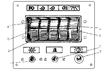
Checking of the intactness of the group of red lamps is carried out by depressing check button 8 on the switch board.
The board also bears a unit made up of five key switches: switches 2,3,5 of working external lighting and switch 6 of the cab interior lighting,also the toggle switches 1,7 energizing the heater fan and flashing beacon.
The fuse links installed in the electric circuits protect the electrical equipment against overloads.
The board of the fuse link units is located on the cab rear wall (at the left as viewed in the direction of the travel), it is closed with a lubrication chart.
Installed under the cab at the left is a socket for connecting the portable lamp.
Instrument board.
This board is arranged in the upper part of the cab front wall.
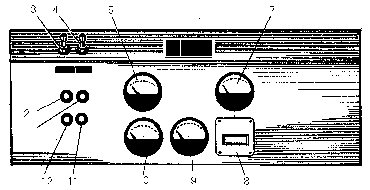
On the board of the motor grader with the YAMZ-8482.10-01 engine are located the following instruments:
engine coolant temperature indicator 5, engine oil pressure indicator 10, air system pressure indicator 7, voltage indicator 9 and hour meter 8.
Available on the board are also two switches 3 and 4 of front and rear windscreen wipers,respectively and the glow-plug preheater pilot lamps.
Storage battery discharge pilot lamp 2 lights up in case the generator is faulty and when the "Frame" is switched on prior to starting the engine. Lamp 11 indicates ignition of the plugs of the glow-plug preheater, while lamp 12 shows that the glow-plug preheater is ready for operation and the starter is switched on.
