Clutch
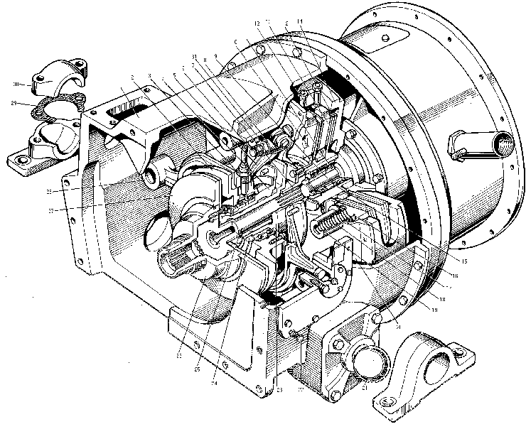
The clutch is designed to ensure smoThe clutch is of a two-disc, dry, spring-loaded type. The driving part of the clutch is journal disc 14 of the reduction gear of the hydraulic pump drive, also discs 13 and 10, the latter serves as a pressure plate at the same time. Each of both discs 13 and 10 has three equidistantly spaced slots, through which they are flexibly connected axially to the disc of the reduction gear of the hydraulic pump drive by means of special slide blocks. Driven discs 12 are fitted between the driving discs. They have toothed rims through which they are connected to drum 11 having the external teeth.

The drum runs in two ball bearings which, in their turn, are installed on journal 9 of the reduction gear of the hydraulic pump drive. The drum has the internal teeth,by means of which it is connected to cardan shaft coupling 7, while the latter is connected to cardan shaft 25.
The cardan shaft has a toothed rim,through which it is connected to gearbox flange 26. Stop 27 with the internal teeth is mounted on the same flange. The stack is compressed with springs 17 and 18,thrusting against the sleeves at one side and against disc 10 seat at the other side through heat insulating pads. The sleeves are inserted into the holes available one flange 20 which is bolted to the disc of the reduction gear of the hydraulic pump drive.The flange mounts clutch release sleeve 2.
The sleeve consists of side 23,one ball bearing nut 24 fastening the bearing on the slide. The bearing outer races are mounted in the housing and covered. The housing is screwed to yoke 28, which thrusts which thrusts with its one end against the bushing fastened in the cover. Thus,some parts of the sleeve do not rotate,while some other parts are rotating together with flange 20. Hinge-connected on the flange are three levers 5, whose lower ends thrust against release sleeve slide 23 through a hardened ring.
Pressure disc 10 has three holes,into which bolts 6 are inserted through which the disc is depressed from the driven disc.The bolts receive knife edges 8 whose tapered portion enters the recesses on levers 5. The knife edges thrust against the castle nuts screwed onto bolts 6.
The clutch operates as follows:
1) the torque from the engine is imparted to the disc of the reduction gear of the hydraulic pump drive,where- from through the slide blocks of the disc to the compressed stack of the discs of the clutch;
2) the driven discs impart the torque to the toothed drum and through the cardan shaft coupling and the cardan shaft to the gearbox primary shaft;
3) when the clutch is disengaged,the release sleeve is shiftted towards the stop.Pressure is exerted onto the ends of levers 5 which act on bolts 6 througt the knife edges and nuts and pull out pressure disc 10.The driven discs can rotate easily relative to the driving ones.The transmission of the torque stops;
4) special stop 27 is provided in the clutch for braking the driven shaft during gear shifting.When upshifting,brace the gearbox driving shaft to equalize the linear speeds of the gears on the driving and driven shafts.Depress the clutch pedal smoothly till effort on the pedal is felt,disengage the gear,depress the clutch pedal till stop (during which the gearbox primary shaft becomes braked), engage the high gear;
5) during downshifting, the brake has a negative effect upon the transmission. In order to obviate the braking of the gearbox primary shaft, the clutch pedal should be pushed only to the moment of sudden rise of resistance. The gear in this case occurs disengaged, while the brake is not still actuated;
6) in order to obtain a more accurate downshifting of the gears, drive up the driven shaft of the clutch by guickly changing-over the gears. To this end, disengage the clutch and set the gear shift lever to neutral position, release the clutch pedal, increase the engine speed, press clutch pedal again and shift the gear shift lever to the lower gear.
Clutch disassembly particulars. Prior to disconnecting the hydraulic pump drive reduction gear casing from the clutch case, remove the cover 32, disconnect the hose and free the tie of the clutch servo mechanism from the pressure clip.
Attention! Observe special care during complete disassembly of the clutch while dismantling the flange 20.
Before unscrewing all the fastening bolts of the flange, screw in at least three studs M12x143 arranged equidistantly over circumference instead of three bolts that secure the flange.
Screw nuts upon the studs, undo other bolts fastening the flange, and then start to undo gradually the nuts on the studs. These precautions should be taken to prevent breakage of the bolt under the action of compressed springs when the last bolts are being unscrewed. Breakage of the bolts may result in an accident.
Adjustment procedure for the clutch includes presetting of a uniform clearance of 0...0.2 mm between the levers 5 and the coupling 2, and adjustment of a 21 mm clearance between the brake 27 and the coupling 2. Adjustment of these dimensions in conjunction with the adjustment of the clutch servo unit is described hereinbelow.


