Pneumatic drive of brakes
On the motor grader are mounted the service and emergency brake drives.The brake pneumatic drive consists of two independent circuits.
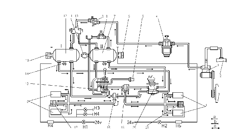
Circuit I of the intermediate axle brake working drive comprises minor receiver 12 with a condensate drain cock available in the frame I.h. side member,lower section of two-section brake valve 20, two-line valve 18 and brake air cylinders 16.

With the pressure drop in the circuit down to 0.45-0.5 MPa (4.5-5 kgf/cm 2) pickup 13 operates, energizing pilot lamp (H1) of the given circuit on the signal panel.
When the brakes are applied,stop signal lamps (H4, H3) light up.
Circuit II of the rear axle brake working drive of the motor grader comprises a receiver mounted in the motor grader frame longitudinal pipe, upper section of brake valve 20, two-line valve 19 and brake cylinders 1. Two condensate drain cocks are mounted in the receiver.
With the pressure drop in the receiver down to 0.45-0.5 MPa (4.5-5 kgf/cm 2) pickup 6 operates, energizing pilot lamp (H2) of the given circuit on the signal panel. The emergency drive is intended for stopping the motor grader in case of failure of working drive of brakes. Components of the circuits of emergency and working drives are the same with the exception that the emergency drive comprises the pneumatic ir distributor 15 with hand control instead of brake valve 20.
1. Brake-released position. Prior to starting movement, fill the pneumatic system of the motor grader with compressed air. Filling of the receivers is checked by the pilot lamps. The lamps should go dark,when pressure reaches 0.5 MPa (5 kgf/cm 2), then start moving. Further filling of the system is checked by the pressure gauge. As soon as pressure reaches 0.69-0.735 MPa (6.9-7.35 kgf/cm 2) the pressure regulator comes into action and the filling stops. Air is discharged into the atmosphere.
The receivers are filled with compressed air under rated pressure. From the receivers the compressed air is fed to the sections of the brake valves and pneumatic distributor.
2. Motor grader braking with the help of the working drive is performed when the brake pedal is depressed. The effort applied by the driver to the pedal is transmitted through a leverage to the brake valve. In this case, compressed air fed from the receiver 7 to the brake valve upper section comes into the wheel brakes of the motor grader rear axle. At the same time compressed air from the minor receiver 12 flows to the wheel brakes of the motor grader intermediate axle through the brake valve lower section. When compressed air is fed to air is fed to air cylinder 38, piston 15, overcoming the force of springs 39, compresses the stask of brake discs. In this case, oil from the spaces between the discs is expelled back into the housing via the grooves in the discs. The surfaces of brake discs 41, mounted on the splines of driving bushing 42, come in contact with the surfaces of discs 40, which are spline-connected to brake housing 13.The braking moment is created due to friction of these discs.
During braking the pedal is released by the driver. Both sections of the brake valve communicate with the atmosp-here.Compressed air from the wheel brakes flows through the brake valve into the atmosphere. When the pressure is relieved from the air cylinder, pressure disc 14 under the action of springs 39 returns into its initial position. As the air pressure is released in the pneumatic cylinder, the pressure plate 14 returns to the initial position under the action of the springs 39. In so doing, the stack of discs becomes released from the pressure, the discs go apart and occurs unbraking.
Thus,when the service brake is applied,two circuits operate simultaneously: circuit I of the intermediate axle brake drive and circuit II of the rear axle brake drive. In case one of the circuits is fault,the other circuit remains operating.
3. Emergency braking of motor grader. The emergency brake drive is actuated in case the brake valve or brake valve drive fails. In emergensy the pneumatic distributor handle 15 located to the left of driver's seat should be moved in rear position. At the same time the compressed air is supplied from the receivers 7 and 12 through the pneumatic distributor 15 the two-line valves 18 and 19 and further on to the pneumatic cylinders of the rear and intermediate axle wheel brakes. In case a circuit fails the other remains operative.
When unbraking the driver releases the handle of the pneumatic distributor so that is returns to the initial position, at the same time the brake pneumatic cylinders become connected with the atmosphere through the pneumatic distributor thus causing the unbraking.


