Steering of motor grader DZ-98B
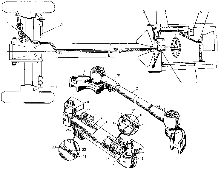
Steering is of hydrostatic type, operates as an independent circuit having the common hydraulic tank 4 and the intake pipe 8.
1- hydraulic cylinder;
2- tie rod;
3- safety valve;
4- hydraulic tank;
5- delivery line;
6- booster;
7- NSH 50 pump;
8- intake line;
9- hydraulic steering wheel;
10- tie rod end piece;
11- front axle rotation bracket;
12- pipe union;
13- sealing ring;
14- rod;
15- collar;
16- piston;
17- stop;
18- seal body;
19- ball pin;
20- lock washer;
21- chevron collar;
22- thrust washer;
23- scraper;
24- cylinder cover
The working fluid is fed into the hydraulic steering wheel 9 by the NSH-50 gear pump. The hydraulic steering wheel ensures depending to the direction of steering wheel turn mounted on it the fluid supply in one of the cavities of the wheel turn hydraulic cylinder 1 and the fluid drainage from the other cavity. At this, the rod of the hydraulic cylinder 1 turns the r.h. rotating bracket of the front axle simultaneoly with by means the tie-rod 2 turns the l.h. rotating bracket. Together with the rotating brackets turn the motor grader front wheels.
The tie-rod 2 connects the rotating brackets 11 of the front axle by means of the ball hinges. To eliminate plays in the hinge make use of a nut which should be first tightened up against the stop, then slackened off to an extent allowing its cottering.
To eliminate plays in the joints make use of a nut, which should be first tightened up home, then slackened off to an extent allowing its cottering.
The tie rod 2 is made adjustable to set the required size of the toe-in. Check the toe-in between the wheell rims on an even ground, setting the wheels for straightforward movement. The toe-in is determined as the difference of dimensions between the inner rims in the front and in the rear on the height of wheel axis. The size along the rim beads in front should be less than the size in rear by 1.5-2.5 mm.


