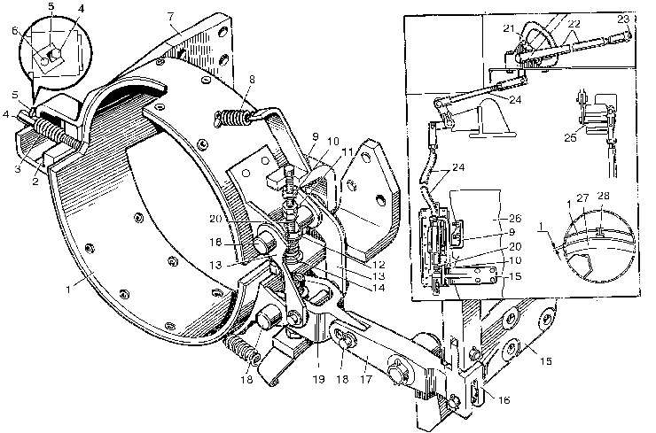
Parking brake of motor grader DZ-98B
The parking brake of the band type is mounted on the transfer reduction gear housing.The brake drum is fitted on the shaft of this reduction gear. The brake serves for braking the motor grader during the standstill or in motion in emergency cases.It is not advisable to apply this brake in motion,since it acts directly on the transmission parts. When lever 22,arranged in the cab, is pulled,the effort is transmitted through the system of levers and ties to lever 19, which in turning around pin 18, pulls up levers 13 connected to the shoes of brake band 1. Due to this,the clearance between the drum and band is taken up and the rotating drum of the transmission and, hence, the motor grader becomes braked.

1- brake band with friction linings;
2- brake band clamp;
3,8- springs;
4- setting screw;
5- locking strip;
6- locking strip fastening bolt;
7,9,15- brake mechanism fastening bracket;
10- locking bolt;
11- nut and locknut of adjusting bolt;
12- washer;
13,19- levers;
14- expansion spring;
16- compensating fork;
17- two-arm lever;
18- pin;
20- adjusting bolt;
21- toothed segment;
22- brake lever;
23- lock button;
24- intermediate tie;
25- shaft;
26- power transmission unit;
27- brake drum;
28- rivet
When the brake lever is released,the clearance between the brake band and drum is set under the action of springs 8. Spring 8 is intended for drawing the band from the drum to ensure a clearance between the brake band and the drum, since without the spring the band under the action of its own mass comes in contact with the drum,causing overheating during operation. The brake lever stroke till complete braking should correspond to four-five teeth on the lever quadrant (to be determined by the number of clicks when turning the lever).Adjust the brake when the number of clicks reaches seven-eight. Proceed with adjusting with lever 22 released completely as follows:
1) undo bolt 6 and remove locking strip 5;
2) turn out setting screw 4,introduce 1 mm thick feeler between the drum and brake band and press the feeler with the said screw so that it can be moved under an effort of 19.6-29.4 N (2-3 kgf). Following this, take out the feeler, reinstall the locking strip and turn in the screw;
3) unscrew locknuts 11 of adjusting bolts 20,insert the 1 mm think feelers between the drum and the brake band upper and lower ends and press them as described above. After that tighten up the locknuts and with draw the feelers.
On completion of the adjustment check the brake for braking effeciency. Concurrently absence of heating is checked.After a 10...15 min of running-in of the motor grader, when the parking brake was not applied, no perceptible heating should be felt by hand.


