Reverse and gear shift mechanism of motor grader DZ-98B
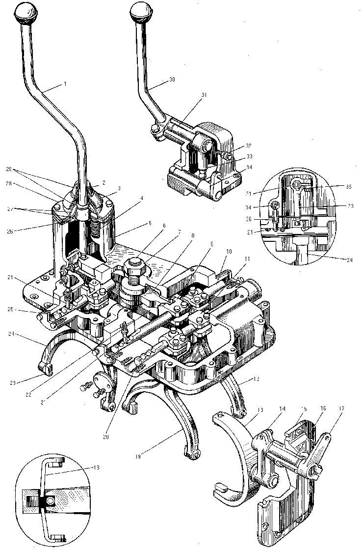
The reverse and gear shift mechanism is mounted on the upper part of the gearbox case. It comprises housing 5, secured on the gearbox case, wherein three shafts of the gear shift and reverse are located.Two shafts 10,20 are similar and serve as the guides for forks 12 and 19 shifting the 1st,2nd and 3rd gears.Shaft 16 serves as a guide for reverse shifting fork 24.Special slide blocks 23 entering annular slots on the external slee ves are fitted on the ends of the forks.

1- gear shift lever;
2- cap;
3,15- covers;
4- spring;
5- housing;
6- axle;
7- nut;
8- I and II gear lever;
9- I and II gear shaft collet;
10- I and II gear shaft;
11- III gear shaft collet;
12- I and II gear engagement fork;
13- step-up gear shift fork;
14- step-up gear fork lever;
16- step-up gear shaft;
17- step-up shaft lever;
18- stop;
19- III gear engagement fork;
20- III gear shaft;
21- lock;
22- III gear lever;
23- slide block;
24- reverse fork;
25,31- reverse shaft;
26- ring;
27- internal ball flange;
28- external ball flange;
29- lever seal;
30- reverse lever;
32- breather;
33- reverse internal lever;
34- interlock mechanism shaft;
35- key;
36- lock spring
All the above forks are fastened on the shafts with a collet-type clamp.Shafts 10,20 are hinge-connected to levers 8 and 22, having common axle 6,secured on the gear shift mechanism housing.The ends of the levers have rectangular slots into which the end of gear shift lever 1 enters.The latter is hinge-connected to the gear shift mechanism housing. Reverse fork 24 has a slot for entry of lever 33, secured on the shaft. The latter is mounted in the cover,fastened on the machined surface of housing 5. Reverse lever 30 is fastened on the other end of the shaft. To preclude the gears and reverse of the gearbox from spontaneous engagement a positive interlocking mechanism is provided. It comprises three locks 21, three springs 36. The locks are overlapped by shafts 34,having holes for entry of the lock tails. Shafts 34 are interconnected through a slot and a prong that enters this slot.
A lever is welded to the ends of shaft. The latter is installed in cover, secured to housing 5, while shaft 34, in the cover. Shaft together with the lever is hinge-connected with tie 9, the latter, in its turn, with lever 10 welded to the shaft.
This shaft is fitted in bracket 11 attached to the gearbox housing.The two-arm lever of the clutch control mechanism is installed on the end of the shaft with woodruff key.Spherical ends of locks 21 enter the slots made on the gear shift and reverse shafts. Each shaft has three slots corresponding to the neutral and two engaged positions. A step-up gear engagement mechanism serves for shifting to high or low gear. It comprises cover 15 secured to the gearbox housing at the l.h.side in the direction of the motor grader travel, fork 13 with slide blocks 23. The fork is hinge-connected to lever 14, secured on shaft 16 which freely runs in cover 15. Lever 17 connected to the gearbox control mechanism tie is secured to the end of the shaft.
The front axle drive is engaged (disengaged) by means of fork 21 with the slide blocks,the fork being secured on the shaft. The latter is installed in cover 24 and is able to move easily in the axial direction.
Fork 21 has a rectangular slot which receives the spherical end of lever 23 secured on shaft 22, the latter being freely mounted in cover 17, secured to the gearbox housing cover at the left in the direction of the motor grader travel. Attached to the end of the shaft is lever 23, hinge-connected to the gearbox control mechanism tie.
During operation of the gearbox the torque from the engine is transmitted through the coupling of the reduction gear of the pump drive and clutch to primary shaft.Further the torque is transmitted through engagement sleeves 2 and 6 to one of gears 3,5 and 7, depending on the gear engaged.The corresponding gear is engaged by the driver by means of lever 1. With its lower end this lever actuates one of two-arm 8 and 22 levers. Lever 8 through shaft 10 and fork 12 engages the 1st and 2nd gears,while lever 22,the 3rd gear. The torque from the primary shaft is transmitted through the driving and driven gears of the corresponding gear to reverse shaft. When external sleeve is displaced towards gear 17 the gear is engaged corresponding to the motor grader forward travel, while gear 26 is engaged for reverse travel. The external sleeve is moved under the action of fork 24. The torque from the reverse shaft is transmitted to layshaft, wherefrom to gears 22 and 24,depending on which gear is engaged. When gear 22 is engaged, the torque on main shaft 21 increases,while gear 24 is engaged, the torque decreases and, as a result, the motor grader speeds up or slows down.
As has been mentioned above the shaft of the forks of the 1st, 2nd, 3rd shifting gears and the reverse fork shaft are interlocked.
In the initial position shafts 10 and 20 are positioned so that the holes for locks are arranged through an angle to the axis of locks 21, therefore they cannot be pushed up from the tapered grooves of the shift shafts,thus precluding the gears from spontaneous disengagement.
During the gear shifting the clutch becomes disengaged,thus disconnecting the engine and transmission and facilitating the gear shifting.When the clutch pedal is depressed, two-arm lever,being rigidly connected to the shaft,turns.The shaft turns the said shafts through lever and tie till such a position,when the axes of their holes coincide with those of the locks.In this position only the gear shifting is possible.


