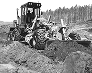
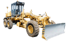
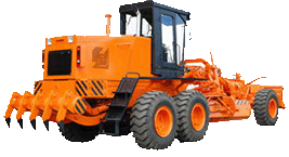
Hydraulic steering of motor grader DZ-98B
The hydraulic steering wheel serves to reduce an effort on the steering wheel, when the front wheels of the motor grader are turned. One of the following models of hydraulic steering wheel is used:1) the Y245006-00-01 hydraulic mechanism of steering wheel;
2) the HDM 200-Y600 monoblock metering pump.
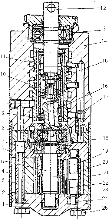 The Y245006-00-01 hydraulic mechanism of steering wheel consists of three elements: distributing unit, planetary reduction gear and close-loop hydraulic motor. The distributing unit incorporates housing 14, slide valve 15, shaft 12, fastened on bearing 13. Bushing 16 is available in central hole of slide valve 15. It is capable of turning through without axial displacement relative to the slide valve.
The involute splines are provided in the lower portion of the bushing, while in the upper one, two guide slots are made to receive pin 11, connecting the shalf and the bushing. Spring 10 installed between the shaft and bushing serves to set the slide valve into the initial position. The planetary reduction gear consists of crown gear 18, satellite 8, attached to eccentric shaft 5 of the hydraulic motor. The distributing unit is connected to the planetary reduction gear by universal-joint 9. The gear rings of the latter with their one end mesh with bushing 16, while with the other end, with satellite 8.
The close-loop hydraulic motor comprises housing 21 sun gear 22, three periphery gears 23 mounted on shafts 19. The central gear through tapered pin 20 is connected to eccentric shaft 5 of the hydraulic motor. Bearings 7 and needle bearings 1 and 24 are located in upper cover 6 and lower cover 2 of the hydraulic motor. Banding 4 ensures tightness of the hydraulic motor. Three pins 3 serve to assemble and align the hydraulic motor. All three elements are coupled by six bolts 25.
The hydraulic steering wheel is connected to the steering hydraulic system through four threaded holes available on the housing of the distributing unit of the hydraulic steering wheel: H-head, CL - drain, L and P-I.h. and r.h. working spaces of the actuating hydraulic cylinder, respectively.
Operation. With the slide valve in the middle position, working fluid, fed by the feeding pump to inlet H of the hydraulic steering wheel via the ducts of the distributing unit flows to the tank for drainage. All the remaining ducts are closed.
As shaft 12 of the hydraulic steering wheel is turned either side, slide valve 15 under the action of pin 11 on the guide slots of bushing 16 moves axially, smoothly overlapping with its edges the distributing unit duct, which connects holes H and CJI. At this, working fluid through the close-loop hydraulic motor flows into one of the cavities of the actuating hydraulic cylinder. The fluid forced out of the opposite cavity is drained into the hydraulic tank.
Eccentric shaft 5 of the hydraulic motor is brought in rotation at the expense of flow of fluid coming into the hydraulic motor and further into the actuating hydraulic cylinder. This shaft by universal- joint 9 through planetary reduction gear (reduction of rotational speed by 15.5 times) turns bushing 16 in the direction of rotation of hydraulic steering wheel shaft 12 with the aim of shifting the bushing and hence the slide valve, via the bushing guide slots axially into the initial position.
As soon as the hydraulic steering wheel shaft stops rotating and is held, axial displacement of the slide valve takes place towards its initial position until the pressure in the system drops down to a value less than the external load and the motor grader stops turning.
When the steering wheel is lowered, the slide valve under the action of spring 10 returns into the initial position and lets working fluid flow from the pump to drainage.
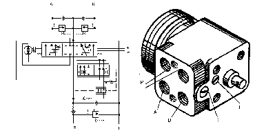
The HDM200-Y600 monoblock metering pump is of self-contained unit design, which consists of hydraulic servo booster and pump-motor. The steering wheel rotation is a input signal of hydraulic booster. Volume of working liquid fed from the metering pump to the hydraulic cylinder of wheel turn is proportional to rotation angle of steering wheel. For connection to hydraulic system the metering pump has four screw holes on the body: P, T, A, B.
When the feed pump operates, the metering pump provides an increased feed of working liquid in comparison with its nominal work volume at the expense of the buil-in amplifier of flow. In emergency mode in the absence of working liquid flow from the feed pump the metering pump operates as a hand-operated pump, which is powered by steering wheel rotation. The latter provides decreased feed equal to its nominal work volume. Thus there is possibility to control the motor grader in emergency mode. The metering pump is made:
- "with open center" - in the absence of controling effect on steering wheel the metering pump feeds the working liquid from the feed pump to the drain;
- "without reaction" - road effect on the wheels is not transmitted to the steering wheel. The metering pump is equipped with built-in valves, which perform the following functions: safety valve - feed pump protection against pressure overload;
return valve - working water discharge prevention at breakage of feed pipeline;
antishock valves - hydraulic system protection against pressure changes by road shock effect on wheels;
antivacuum valves - replenishment of opposite cavity of hydraulic cylinder at antishock valve operation and cavitation suppression.
Adjustment pressure of the safety valve is of 16▒0,5 MPa (160▒5 kgf/cm2), the antishock valves-of 21 MPa (210 kgf/cm2). If necessary the adjustment pressute is checked in the same sequence that is presented in the subsection 2.5 "Hydraulic system of motor grader".
ATTENTION! ADJUSTMENT OF THE SAFETY VALVE AND THE ANTYSHOCK VALVES IS PERFORMED, IF NECESSARY, ONLY AFTER TERMINATION OF THE MOTOR GRADER WARRANTY PERIOD.
The safety valve is adjusted by turning the screw 1. Both the antishock valves are adjusted by turning the screw 2.
