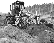
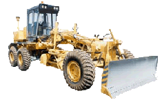
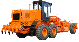
Hydraulic distributors of motor grader DZ-98B
The hydraulic distributors are designed for controlling the working fluid flow and its distributing between final-control devices of hydraulic system.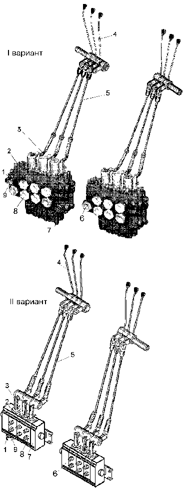 On the motor grader are installed two hydraulic distributors.
 1- cap;
2,6- pressure sections;
3- slide valve;
4- lever;
5- tie;
7- drainage section;
8- working section;
9- locknut
Each hydraulic distributor has three working sections 8 with the non-return valves, the pressure section 2 or 8, the discharge section 7. The hydraulic distributors are different from each other by the presence of the safety valve and the by-pass valve in the pressure section 2, with are absent in the pressure section 6. One of the following modifications of the hydraulic distributors is used:
1st modification - the 538-4612009 DH and 538-4612010 DH hydraulic distributors;
2nd modification - the PC 25.20-20-3x0.1-30,1 and PC 25.20-20,1-3x0.1-30 hydraulic distributors;
3rd - the DZ-98B.43.09.010 and
DZ-98B.43.09.010-01 hydraulic distributors.
All these three modifications of installation of the hydraulic distributors in the hydraulic system are interchangeable and differend only by the control mechanism design of the slide valves 3. Slide valves 3 of the distributor move with the help of ties 5 connected to control levers 4. The slide valves may occupy three positions: "Neutral", "Lifting" and "Lowering", while the neutral position is a fixed one.
As soon the control lever is released by driver, the slide valve returns into the neutral position with the aid of a spring.
The by-pass valve of section 2 directs the fluid flow for drainage into the hydraulic tank with the slide valves in the neutral position.
The safety valve limits the maximum pressure in the hydraulic system actuating when the adjustment pressure is exceed and together with the by-pass valve ensures drainage of fluid at a pressure exceeding the valve adjustment pressure. The safety valve has an adjusting screw closed with cap 1.
ATTENTION! UNSEALING AND ADJUSTMENT OF THE SAFETY VALVE IS PERFORMED NECESSARILY ONLY AFTER TERMINATION OF THE MOTOR GRADER WARRANTY PERIOD.
To regulate pressure remove cap 1 and release locknut 9 from the screw.
Requirements for checking and adjustment of pressure see above in the item "Checking and adjustment of pressure".
1- carrier;
2- body;
3- cover;
4,5- sealing rings;
6- axle
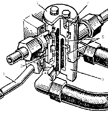
A hydraulic adapter serves for preventing the mould board overhang hydraulic cylinder from twisting of the hoses, when the mould board turns in the horizontal plane. The oil lines of the hydraulic system distributor are connected to the hydraulic adapter unions mounted on fixed body 2.
The hoses of the mould board overhang hydraulic cylinder are connected to the unions of movable axle 6 which rotates in body 2 by means of carrier 1. Such a design ensures easy turning of the mould board together with the hydraulic cylinder as well as a reliable operation of the high-pressure hoses.
